Hoj!
Tack för input!

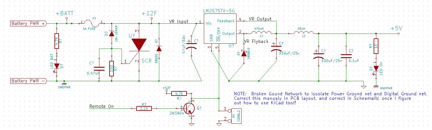
Jag har inte dött, PSU ligger på is en liten stund tills jag får behov av en och vet mer om vad den behöver hantera för last.
Under tiden har jag satt upp ett 2nods CANbus-nät, utökat libraries till arduino och jag jobbar på addresseringen just nu.
En första skiss på addressplanen:
Kod: Markera allt
Standard CAN V2.0A
11bits id    | RTR | R1 | R0 | DLC  | Data (0-8B)
000 00000000 |  0  | 1  | 1  | 0000 | 00000000 00000000 00000000 00000000 00000000 00000000 00000000 00000000

Extended CAN V2.0B
The reserved R1 is moved further down, IDE is set in it's place to lets the host know that it's a V2.0B Frame.
SRR is 0 to ensure that if there's a V2.0A frame with RTR set sent the Data frame will get priority.
11bits id    | SRR | IDE | 18bits identifier    | RTR  | R1 | R0 | DLC  | Data (0-8B)
000 00000000 |  0  | 1   | 00 00000000 00000000 | 0    | 0  | 0  | 0000 | 00000000 00000000 00000000 00000000 00000000 00000000 00000000 00000000

My Standard..
Pri | 8bits sID | SRR | IDE | 10 bits function   | 8 bits dID | RTR | R1 | R0 | DLC  | Data (0-8B)
000 | 00000000  |  0  | 1   | 00 00000000        | 00000000   | 0   | 0  | 0  | 0000 | 00000000 00000000 00000000 00000000 00000000 00000000 00000000 00000000
ID is 8bits, the master is given a low ID to get priority if multiple nodes tries to send with the same priority at once.
ID is programmed by an 8-bit dip switch, or written to flash.
sID is Source ID.
dID is destination ID.
Pri is Priority, 0-7 where 0 is the highest.
function is the function i wan't to call.
Bit 0 is the rightmost one, Bit 7 is the leftmost bit.
Bit 0:
ID 0 is used for bus clock (if clock missing for more than 100ms all nodes should enter failsafe mode / safe shutdown and wait for master to resume clock)
ID 1 is reserved.
Bit 2-0:
ID 2-7 is reserved for master node(s)
Bit 3-0:
ID 8-15 Critical Priority nodes (Brakes.. won't be implemented ... yet..)
Bit 4-0:
ID 16-31 Very High Priority nodes (Reserved bits...)
Bit 5-0:
ID 32-63 High Priority nodes (Lights, Ignition..)
Bit 6-0:
ID 64-128 Low Priority nodes (Starter, Air Suspension, Winch activation)
Bit 7-0:
ID 128-255 Measurement nodes (Temperature, Voltage, ride height)
00000000 Clock
00000001 Reserved
00000010 Master1
00000011 Master2
00000100 Master3
00000101 Master4
00000110 Master5
00000111 Master6
00001000 Crit Pri 1
00001001 Crit Pri 2
00001010 Crit Pri 3
00001011 Crit Pri 4
00001100 Crit Pri 5
00001101 Crit Pri 6
00001110 Crit Pri 7
00001111 Crit Pri 8
00010000 Very High Pri 1
00010001 Very High Pri 2
00010010 Very High Pri 3
00010011 Very High Pri 4
00010100 Very High Pri 5
00010101 Very High Pri 6
00010110 Very High Pri 7
00010111 Very High Pri 8
00011000 Very High Pri 9
00011001 Very High Pri 10
00011010 Very High Pri 11
00011011 Very High Pri 12
00011100 Very High Pri 13
00011101 Very High Pri 14
00011110 Very High Pri 15
00011111 Very High Pri 16
00100000 Medium Pri 1
....
00111111 Medium Pri 32
01000000 Low Pri 1
....
01111111 Low Pri 64
10000000 Measurement/Others 1
....
11111111 Measurement/Others 128
Jag klurar på hur jag ska fördela 10 Bits Function nu, och vad jag egentligen vill uppnå med de bitarna. Jag har ju möjlighet att sätta flera funktioner på samma nod (lyse, start och tändning är ett exempel, Bromsljus, blinkers och luftfjädring är ett annat..), i det fallet skulle dom ju dela ID.
Idéer?