Vittja data från trådlös elmätare

Berätta om dina pågående projekt.
kng
Inlägg: 28
Blev medlem: 20 december 2010, 19:11:00
Ort: Umeå

Re: Vittja data från trådlös elmätare

Inlägg av kng »

Har gjort ett testprogram som försöker dekoda datan jag får från sniffern nu, det verkar funka hyffsat iaf.

Perlscript som dekodar (ursäkta variabelnamnen):

Kod: Markera allt

#!/usr/bin/perl -w
use strict;

my @data;
my ($shit,$ch,$max,$curr,$acc);;

while(<>){
    s/[^0-9a-fA-F\s]//g; # filter the message to contain only hex numbers
    next if(length()!=54); # wait for the correct length row
    if(/^A0 (00|30|60|90|C0|F0)/){ # look for a write to the right address
        @data=split(" ");
        $shit=join("",reverse(@data[2..10])); # cut out the interesting part
        print "Raw: ".$_;
        $ch = hex($data[1])/48 +1; # calculate the channel number
        $max=hex(substr($shit,13,4))/10;
        $curr=hex(substr($shit,9,4))/10;
        $acc=int(hex(substr($shit,1,8))/3600);
        print "CH".$ch." Max: ".$max." W    Curr: ".$curr." W    Acc: ".$acc." Wh\n\n";
    }
}
Rådata jag får fram av en SCAN:

Kod: Markera allt

A2 C0 A3 E2 42 A2 38 55 27 38 26 FF FF F3 FF FF FF FF F3 FF FF
A0 44 A1 00 01
A0 30 00 00 00 00 40 17 09 4D 00 00 00 B0 DD 0C 00 B0
A0 40 2A 22 8A 93
A0 44 00 01
A4 40 A6 80 00 00 00 00 F5 00
A0 74 A1 80 01
A0 60 A4 A4 90 0C 10 3E 4C 8E 00 00 00 80 87 00 00 F0
A0 70 C7 53 75 92
A0 74 80 01
A4 70 3C 00 00 00 00 00 45 70
A0 A4 A1 80 01
A0 90 47 20 03 0C 10 4D 4C 85 00 00 00 20 40 0D 00 20
A0 A0 40 8D 63 92
A0 A4 80 01
A4 A0 C6 20 00 00 00 00 C6 C0
A0 14 A1 80 08
A0 00 54 2C E0 01 90 A9 58 03 00 00 00 90 F2 0D 00 60
A0 10 36 25 2E 94
A0 14 80 08
A4 10 01 00 00 00 00 00 0F 00
A0 60 A1 A4 A4 90 0C 10 3E 4C 8E 00 00 00 80 87 00 00 F0 C7 53 75 92
A0 74 A1 80 01
A4 70 A5 3C 00 00 00 00 00 45 70
A0 76 A1 21 3B 45 00 00 00 00 1A 07 3C 00 00 00 00 00 20 83 4A 8E 00 00
Resultatet man får ut om man matar den med rådatan:

Kod: Markera allt

# ./decode.pl example.log
Raw: A0 30 00 00 00 00 40 17 09 4D 00 00 00 B0 DD 0C 00 B0
CH2 Max: 0 W    Curr: 0 W    Acc: 22438 Wh

Raw: A0 60 A4 A4 90 0C 10 3E 4C 8E 00 00 00 80 87 00 00 F0
CH3 Max: 263.4 W    Curr: 20.1 W    Acc: 41447 Wh

Raw: A0 90 47 20 03 0C 10 4D 4C 85 00 00 00 20 40 0D 00 20
CH4 Max: 1280.4 W    Curr: 19.2 W    Acc: 38825 Wh

Raw: A0 00 54 2C E0 01 90 A9 58 03 00 00 00 90 F2 0D 00 60
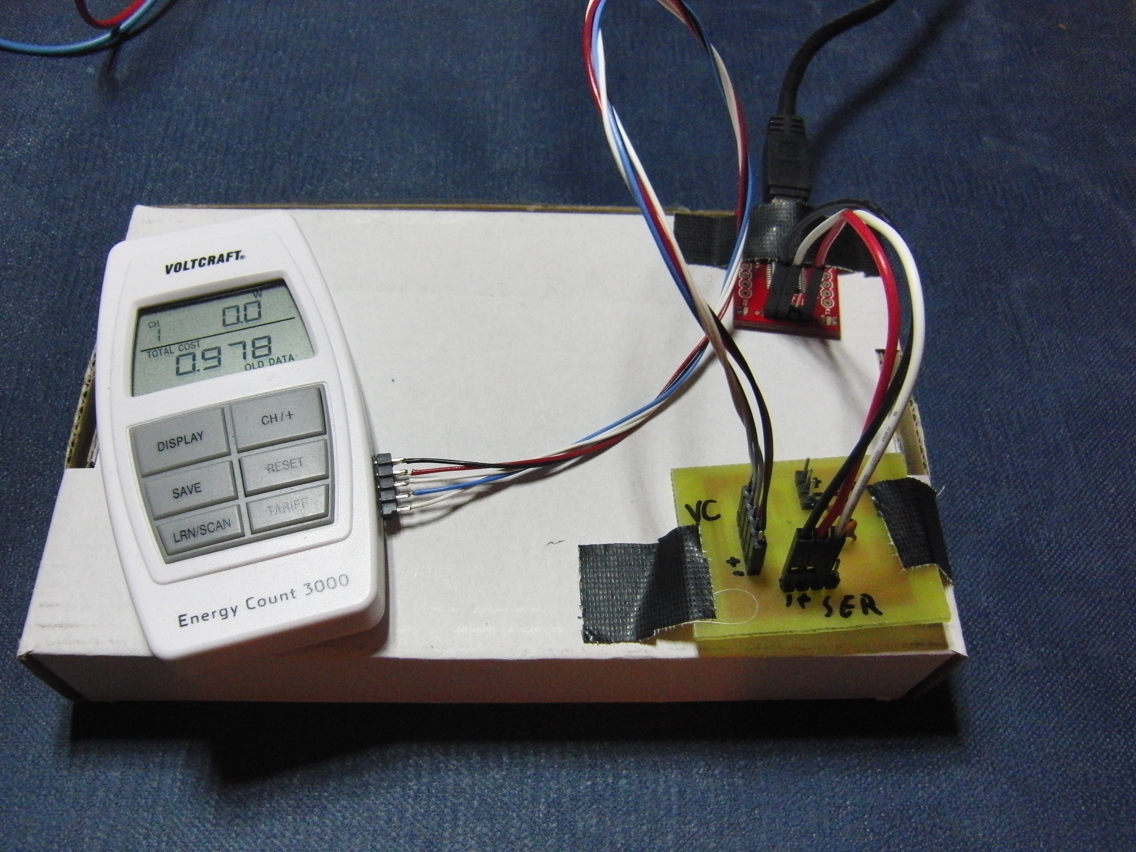
CH1 Max: 70.9 W    Curr: 3 W    Acc: 974 Wh
Första tecknet i datan hittar jag ingen användning för, den verkar öka lite nu och då och inte ha något med själva värdena att göra.
Den enda som inte stämmer är CH4 där ackumulerad effekt inte är 38,8kWh utan närmare 187,9kWh... 41,4kWh på CH3 stämmer däremot bra.. lite skumt.
Om man tar 0x0854C4D1 och lägger till en tvåa i början, 0x2854C4D1 så blir det 187,956kWh... vart man ska få tvåan ifrån är dock fortfarande en gåta.
kng
Inlägg: 28
Blev medlem: 20 december 2010, 19:11:00
Ort: Umeå

Re: Vittja data från trådlös elmätare

Inlägg av kng »

Har gjort ett litet kretskort med i2c-sniffern nu, som är kopplat till voltcraft dosan och till en FT232R breakout.
Den matas i nuläget från FT232 kortet med 3.3V och den verkar då inte klaga.
Schema och kort finns i PDF.

Jag bytte upp mig till en Tiny85 med 14.7456MHz kristall, samma som användes i i2csniff projektet. Det fungerade dock klanderfritt med en Tiny25 och 11.0592MHz kristall.
Sen har jag använt en optokopplare för att trycka på SCAN-knappen med, men har ännu inte bestämt mig på vart exakt den ska på FT232-kortet.. DTR var en variant, TX är inte helt omöjlig om man gör en pulsförlängare, t.ex med en kondensator på knapp-sidan..

Lite bilder från projektet som det ser ut nu:
Bild
Bild
Bild
Bild
Bild
LasseT
Inlägg: 4
Blev medlem: 13 januari 2011, 23:09:43

Re: Vittja data från trådlös elmätare

Inlägg av LasseT »

Mycket spännande!

Var ha du tänkt att lagra datat? Direkt till datorn via USB eller minneskort eller vad?
kng
Inlägg: 28
Blev medlem: 20 december 2010, 19:11:00
Ort: Umeå

Re: Vittja data från trådlös elmätare

Inlägg av kng »

Först och främst logga till dator, då jag är mest intresserad av live-data.

Har aldrig fått tummen ur att låta en atmega snacka med SD-kort, trots att jag lött ett sådant labbkort sedan länge.
Dock handlar det ju mest om att lyssna på tiny85'an och låta en till atmega lagra det om man så vill. För som jag läst så är det inte lätt att få en atmega att lyssna på I2C utan att störa, så man måste ha en tiny med USI som lyssnar på I2C och gör om det till asynkront seriellt eller nått och låta en annan mikro lagra det.
markusrr
Inlägg: 3
Blev medlem: 6 april 2011, 11:10:10

Re: Vittja data från trådlös elmätare

Inlägg av markusrr »

Hello kng,

excellent work so far! - I was following your thread using Google translate since I do not speak Swedish and that's why I'm writing in English. Google translates surprisingly well...

I am working on the same problem, but with a little different approach: My goal is to use my "CUL" (an open-source 868 MHz USB-Stick Transceiver from busware with the CULFW firmware project for the FHEM home automation server) for reception of the RF-data. Have you spent time analyzing the data exchange between the µC and the transceiver? Are you or anyone here on the forum interested in that as well? - I would try to summarize my findings for you in that case.

At the moment I am trying to identify the transceiver chip (my first guess is that it is a HOPE RFR-12B). I agree in the pinning you found. It seems the SPI is used for control of the transceiver and the "RAW" data line transmits the actual received data. Currently I am working with a oscilloscope which makes analysis a little difficult since it has limited storage capabilities and no SPI analyzer support. Have you made a trace with your logic analyzer on these 4 pins during the reception of data which I could analyze? I will get an old HP 400MHz logic analyzer (a really old one, booting it's OS from 720kB floppy) in a couple of days but I can't wait to start work analyzing. Maybe you even have a trace from the "power on" sequence as this would be very helpful in guessing the transceiver model by analyzing the registers they use and comparing that to datasheets...

Regards

Markus
kng
Inlägg: 28
Blev medlem: 20 december 2010, 19:11:00
Ort: Umeå

Re: Vittja data från trådlös elmätare

Inlägg av kng »

Good to know that others are interested in reversing these devices (:

I browsed for some 868MHz modules but didn't find any promising, probably due to lack of knowledge about them.
I've got some recordings from the bus that I have uploaded earlier, you can open them in the freely availible Logic program.
Make sure your browser doesn't rename the files btw...

http://www.saleae.com/downloads/ (the 1.1.4 version works with the '.logicdata' files)
http://www.kng.se/voltcraft/all_lines_01.logicdata

That recording contains a powerup and a completed scan on all the interesting signals, there are other files you can download in that voltcraft/ directory.
As far as I can see, neither the SPI bus nor the radio gets powered up in the boot process, it only activates them with a scan.
About the SPI protocol, I havent done any serioous work on it since I decided to take the I2C route.

Keep us posted on your progress (:
markusrr
Inlägg: 3
Blev medlem: 6 april 2011, 11:10:10

Re: Vittja data från trådlös elmätare

Inlägg av markusrr »

Hi there,

last Wednesday I saw that the Energy Count 3000 is still sold at Conrad Electronic here in Munich and started to play around with it again. It has been some time but I am still trying to find a solution for directly receiving the data.

Risking my logic analyzer's and laptops lives, I made eight logic-traces from the sender an receiver in parallel. The problem is that the sender does not have a isolating power supply of course, ground is tied to one of the 230V connectors. Trust in my isolating transformer is one thing, touching a potential high-voltage keyboard another... ;-)). So my Laptop ran on battery and I "isolated" myself by using wireless keyboard and mouse.

Everything went fine -> Seems the RF chipset is capable of transmitting data using an own baud-rate generator: Looking at the SPI traces of the Sender and Receiver, I found the same data you found when the receiver stores it in eeprom. On the receiver side it is an integrated receiver as well: The line you marked "RAW" in one of your pics above is a interrupt-line or something similar, the data itself is polled from the receiver on the SPI.

The problem is -> I do not have any clue what chipset this is. I hoped to be able to identify the type by looking at the initialization commands the µCs issue to the transmitter or receiver and then interpreting the init-commands to learn the exact RF properties. BUT: Hope RF, TI, Amiccom, SiLabs, Analog, RFM and rfsolutions all have one in common: Their registers do not fit the energy count's init commands (at least I think that ;-)).

So I put my readings on my server an hope anyone out there will by chance recognize the commands: http://zahl42.de/wp-content/uploads/201 ... t_3000.zip (12MB).

This is the init command sequence (interpreted MSB first, could be LSB es well, but makes more sense with MSB...). It is always 2 bytes long. I guess the first bit is the "write" bit, this means one should subtract 0x80 from the first byte to get an "command" or "address". There is one line (starting "0x2D") which seems to be a read, the "data" 0xFF is only idle on the MOSI-line. In parallel with every start of transmission to the transmitter it seems to send its "status" or something as it starts sending data to the µC with the first edge of the clock without even knowing the command already on MISO.

Kod: Markera allt

Time [s]	ID	MOSI	MISO
4,4886772	0	0x82	0x07
4,4887101	0	0x05	0x00
4,4887544	1	0x82	0x07
4,4887873	1	0x65	0x05
4,4918868	2	0xA0	0x07
4,4919197	2	0x36	0x36
4,491964	3	0xA1	0x07
4,4919969	3	0x44	0x44
4,4920413	4	0xA2	0x07
4,4920742	4	0xCC	0xCC
4,4921185	5	0xA3	0x07
4,4921514	5	0xCD	0xCD
4,4921958	6	0x82	0x07
4,4922287	6	0x6C	0x65
4,4923755	7	0xAD	0x07
4,4924084	7	0x18	0x08
4,4925529	8	0x2D	0x47
4,4925858	8	0xFF	0x48
4,4926373	9	0x82	0x47
4,4926702	9	0x6D	0x6C
4,4927146	10	0x84	0x47
4,4927475	10	0x03	0xC7
Sending data byte looks like this. First a read command is issued probably checking the transmit readiness (0x04) and then the data to be sent is written using 0x85-commands. In total 68 bytes are sent, I pastes only the first byte (0xAA, intermittent 1 and 0 for receiver-sync).

Kod: Markera allt

Time [s]	ID	MOSI	MISO
4,492798	11	0x04	0x47
4,4928309	11	0xFF	0xC7
4,4928829	12	0x85	0x57
4,4929158	12	0xAA	0xAA
Maybe someone has seen something like this before.

I will start to "tune" a RFM12B transceiver to random receive-settings (From the duration for the transmission in the trace I guess 20kHz, 868MHZ an I will start with FSK). Mybe I will be able to decode something. At least the data I am looking for is known.

Help appreciated ;-)

Markus
markusrr
Inlägg: 3
Blev medlem: 6 april 2011, 11:10:10

Re: Vittja data från trådlös elmätare

Inlägg av markusrr »

Hi,

maybe you are interested that now there is a solution to receive the RF-Signal using the JeeLink USB Stick.

See here: http://forum.jeelabs.net/node/3414658.htm
Here: http://forum.fhem.de/index.php?t=msg&goto=92109&rid=0
and here: https://groups.google.com/forum/#!topic ... rOMlUHfMjw

Cheers

Markus
Användarvisningsbild
SeniorLemuren
Inlägg: 8374
Blev medlem: 26 maj 2009, 12:20:37
Ort: Kristinehamn

Re: Vittja data från trådlös elmätare

Inlägg av SeniorLemuren »

Har alla plötsligt glömt att detta är ett svenskt forum? Jag har inga problem med engelska, men andra medlemmar kan ha det. Så skippa engelskan. Kan man inte svenska så får man använda Google translate eller något annat för att kommunicera på Svenska.
Skriv svar