


50 Volt låter lite vid 9000 varv, men det blir kanske inte mer med den typen av generator.
en bilgenerator ger minst 100 Volt utan regulator.
i USA använder man ofta en bilgenerator i hembyggda elverk.
Spänningsregulator för MC
Det är en Suzuki GSX 750 EF -84.
Enda skillnaden mellan en sån och MC-generatorn är att den senare inte har kommutator. Den borde alltså följa samma princip.
På en vanlig permanentmagnets DC-motor/generator är varvtalet och obelastade spänningen direkt proportionella.Mindmapper skrev:Någon som vet! Stämmer det att spänningen ökar linjärt med varvtalet?
Enda skillnaden mellan en sån och MC-generatorn är att den senare inte har kommutator. Den borde alltså följa samma princip.


Brorsan hade samma problem med sin GSX750ES för många år sedan. Jag tror det slutade med att han köpte en piratregulator istället. Han hade iallafall inga ytterligare problem med det.
Det verkar som att det är ett ganska vanligt problem. Även på t.ex Honda VFR, som annars inte verkar ha några svaga punkter, så är det problem med regulatorerna.
Det verkar som att det är ett ganska vanligt problem. Även på t.ex Honda VFR, som annars inte verkar ha några svaga punkter, så är det problem med regulatorerna.

Själv har jag lite svårt att köpa att man kortsluter lindningarna när det blir hög spänning - borde bli strömmrusning och brända lindningar tycker jag.
- nyttjar man någon form av kärnmättning mha. DC-ström i generatorkärnan iom. pulsvisa kortisen tro?? Det är liksom inga svaga små permanentmagneter som snurrar i dessa motorer och i mina ögon borde producera en väldigt massa ström när lindningarna kortsluts...
- nyttjar man någon form av kärnmättning mha. DC-ström i generatorkärnan iom. pulsvisa kortisen tro?? Det är liksom inga svaga små permanentmagneter som snurrar i dessa motorer och i mina ögon borde producera en väldigt massa ström när lindningarna kortsluts...
Kärnan mättas och strömmen blir därför ganska måttlig. Det är enklare att hantera den strömmen än de höga spänningar man skulle få annars, isoleringen lämnar en del att önska på en offroadhoj som dränks i något lerkärr varje helg... 
Hittade en del formler och diagram någonstans för beräkning av omlindning av dessa generatorer (nuvarande utspänning och ström vs. det man får efter omlindning med annat antal lindningsvarv) och räknade en del på en mopedgenerator jag ska linda om. Minns inte siffrorna exakt, men jag tror att jag fick fram att jag borde få ut runt 13V och 7A normalt med det varvantal jag tyckte var lämpligast, och att kortslutningsströmmen slulle bli runt 9A eller något liknande.
Hittade en del formler och diagram någonstans för beräkning av omlindning av dessa generatorer (nuvarande utspänning och ström vs. det man får efter omlindning med annat antal lindningsvarv) och räknade en del på en mopedgenerator jag ska linda om. Minns inte siffrorna exakt, men jag tror att jag fick fram att jag borde få ut runt 13V och 7A normalt med det varvantal jag tyckte var lämpligast, och att kortslutningsströmmen slulle bli runt 9A eller något liknande.
Hmm - det betyder att generatorn går nära mättnad hela tiden även vid normaldrift om den börja trippa redan vid några ampere över normllast...
Alternativt en relativt en stor induktans som inte har något med generatorns permanentmageters fält att göra med och man får samma reaktiva begänsning av ström på samma sätt som en skärmspolemotor med låst rotor eller drosseln i lysröret när glimmtändaren kortsluter... - eller tänker jag galet nu...
om sistnämda gäller helt eller till en del så förstår jag varför man inte vill bryta upp slingan - skulle bli väldigt fina induktionsspänningsspikar då...
---
Om dom där formlerna är lättillgängliga så är jag intresserad av en kopia eller länkar dit - har nog för lite fantasi vad jag skulle skriva i googles sökfält på engelska för att få fatt på just sådan information!
Senast redigerad av xxargs 7 april 2007, 22:16:44, redigerad totalt 1 gång.
Efter lite huvdkliande fick jag fram det igen... http://www.advrider.com/forums/showthread.php?t=189734
Här är första inlägget, men jag rekommenderar läsning av hela tråden för er som har intresse av el och mc.
Här är första inlägget, men jag rekommenderar läsning av hela tråden för er som har intresse av el och mc.
It seems that a lot of people want more electrical power on their bikes. The standard procedure is to rewind the stator with thicker wire and take a guess about the number of turns. I am an electrical engineer, but had very little knowledge of electromechanics (motors and generators). I did some reading on how stators actually work, made a few measurements on my own bike and came up with some basic formulas to calculate stator output over rpms for various winding configurations.
Here is what I've learned. I think it applies to all permanent magnet generators (both 2 and 3 phase) like in most motorbikes, but not to generators with a field winding like in a car or a BMW R or K bike.
I'm going to start out using the Honda XR as an example, because that's the bike I've done a bunch of measurements on. I'm going to move to the LC4 because I just bought one, and because there is some very useful information already available about it.
I'm going to start with a very basic electrical model of a stator. By model, I mean a mathmatical description of its behavior. The first rule of models is this: "All models are wrong, but some are useful". By making the model more complicated we could get a better idea of how the generator will work, but I think that this model is pretty close to reality and I want to keep things simple. The calculations and graphs are included in this spreadsheet:
<STATOR_REWIND.XLS></STATOR_REWIND.XLS>stator_rewinding.xls
Start by changing the parameters in pink to see how the results change.
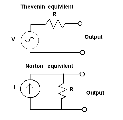
A stator behaves like an ideal voltage source with a series resistance. The voltage is proportional to the engine RPM and the number of turns in the winding, the resistance is proportional to the engine RPM and the square of the number of turns in the winding.
This is equivilent to a circuit consisting of a current source in parallel with a resistance.
<STATOR_EQUIVILENT.PNG>
In the diagram above, the 'Thevenin equivilent' is the voltage source version and the 'Norton equivilent' is the current source version. The Value of V is A * engine_speed * number_of_windings, R is B * engine_speed * number_of_windings^2, and I is A / ( B * number_of_windings). A and B are constants that depend on the properties of the stator core and the flywheel magnets.
Note that R is not the winding resistance- it actually comes from the resistance in the magnetic circuit that is formed by the flywheel magnets, the stator core, and the little gap of air between them. The winding resistance is small compared to this, so I am lumping it into "regulator and wiring losses" which I will go into later. Remember: "All models are wrong...".
In the case of the XR at idle (1200rpm) V is 30V, I is 6A, and R is 5ohms.
This means that if you let the motor idle with the stator disconnected and attach a voltmeter to the stator connector it should read 30 volts- this is called the open-circuit voltage. If you short circuit the stator output through an ampmeter it should read 6 Amps- this is called the short-circuit current. If you double the rpms to 2400, the oc voltage should increase to 60V and the sc current should stay the same at 6A.
In practice, the current will increase slightly as RPM increases- this is due to the winding resistance. Short circuiting the stator does no harm- that's how the regulator works. The stator also acts funny when it is open-circuited- there are large short voltage spikes that show up at the peak of the waveform. Even a very light load (20 ohms) gets rid of them, but they may confuse some multimeters. The behavior with loads between short and open circuit confims the model, though.
Power delivery:
Basic circuit theory says that we will get the maximum power output from the stator when the load is the same resistance as the source. Since the load isn't quite resistive, let's rephrase that to say we get the most power when the load causes the source's output voltage to drop to half the open-circuit voltage. Unfortunatly the source voltage changes with the engine speed. This means we can only optimize for one engine speed. The normal thing to do is optimize for idle, when the least amount of power is available.
For bikes the load is around 15V. That's 13V to charge the battery plus 2V for wiring and rectifier losses. So the XR stator at idle delivers (30V-15V)/5ohms = 3A at idle. The lights need 35W+5W/13V = 3A. It looks like Honda designed the system perfectly. In fact, the stock system has no rectifier, so there is a margin of error built in that is taken up by the aftermarket rectifier in the dualsport kit.
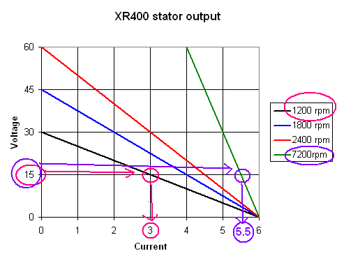
Above idle, the stator puts out more power. At 2400rpm, Voc is 60V and R is 10ohms, so the output into 15V is (60v-15v)/10ohms or 4.5A. At 7200rpm, Voc is 180v, R is 30 ohms so the output is (180v-15v)/30ohms or 5.5A.
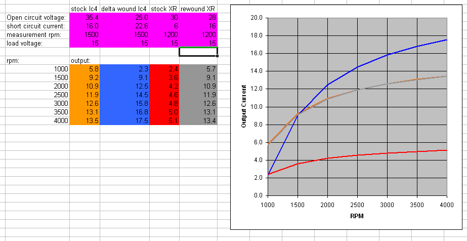
For visual folks, here is a graph of the stator output:
<OUTPUT graph.png="">
For each engine speed, there is a different line of current vs. voltage. To see how much current is delivered, look at the current value where each line crosses 15V. This is how much current the stator will put out at 15V.
The magic numbers:
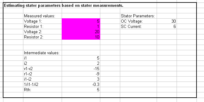
So where did the OC Voltage, SC current and Resistance numbers come from? In the case of my XR, I disconnected the stator wires, hooked them up to load resistors, measured the voltage, and made a spreadsheet. To get the three parameters you only need to make two measurements at a single rpm (if you go back to the equivilent circuits, it's realy only two parameters: A and B). I made a lot more, but that was to confirm that the stator was behaving linearly.
Measuring the open circuit voltage is not recommended due to the strangeness of the coil's behavior without any load. It is hard to find a current meter that can handle the high currents of a short circuit. Use two different value resistors (Say 1 ohm and 10 ohm) and measure the voltage across them
at a single rpm. Plug the voltage and ohm values into the spreadsheet and it will give you OC voltage and SC current. R is just OCV/SCC.
<STATOR_AC_ESTIMATE.PNG>
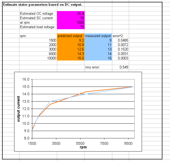
What if you can't run the bike with the stator disconnected? Measure the rectifier output at several different rpms and then choose parameters that would give a similar output. The LC4 iginition is powered by one phase of the lighting coil- unhooking the regulator will result in high voltage hitting the CDI box with potentially bad results. Flanny contacted KTM and got a table showing regulator output vs. rpm. Plugging those numbers into the spreadsheet gives us a good guess of the regulator parameters. The good news is that a curve fits to within 1/2A at every point using reasonable numbers for parameters. The table from KTM was rounded to the nearest 1 amp.
<STATOR_DC_ESTIMATE.PNG>
Improvements:
With the XR, improving the stator is easy- pull the windings off and rewind using the same number of turns as stock (300) using all 10 of the stator poles instead of just 4. This keeps the OC voltage the same, increases the SC current by 2.5x and reduces the resistance by 2.5x. So now the SC current is 15V and R is 2 ohms at idle. As a bonus, there are now only 30 turns of wire on each pole instead of 75. This allows the use of much fatter wire, lowering the resistance of the windings.
Suppose there weren't an extra 6 poles on the stator waiting for us to use. We could try increasing the number of turns in the windings. How about 20% more, say 360 total. Our OC voltage goes up, now it's 36V at idle. Unfortunatly our SC current goes down to 5A and our resistance goes up to 7.2ohms. So now our output power at idle is (36V-15V)/7.2ohms or 2.9Amps. Oops. At 2400rpm we get 4A. Also no good.
Let's go the other way to the extreme. Cut the number of windings in half to 150. Now we get absolutely nothing at idle. But, we get 6A at 2400 rpm, 8A at 3600rpm. Hello. Stick a battery on this thing and we can now run a 60W bulb (just don't get stuck in traffic).
What are we doing here? By changing the number of windings, we are changing the engine speed where the output power is optimized. With our +20% example, the power is optimized at 1000rpm, where we never run. With our -50% example, the power is optimized at 2400rpm. At lower engine speeds we give up power, but at higher speeds we get much more.
If you look at the 'Estimating output' tab of the spreadsheet, you can adjust the OCV and SCC and see what changing the number of windings will do for output over the rpm range.
<STATOR_OUTPUT_ESTIMATE.PNG>
On my XR I underwound the stator slightly- 280 turns total on 10 poles. This reduced the OC voltage a little but gave extra power everywhere above 1500 rpm. It's kinda pointless because I don't need the power at the moment. It is also putting a little extra stress on the regulator. By total coincidence, the output curve for my stator is a dead match for the stock LC4 output. Go figure.
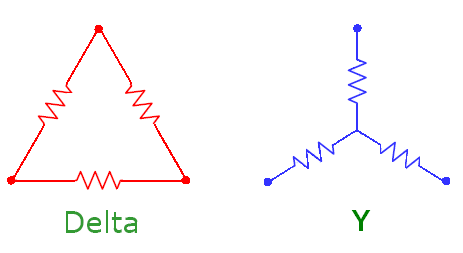
The LC4 stator is 3-phase, which may lend itself to a big change with very little effort. By changing the connection to the windings- without changing the windings themselves it is possible to change the output of the windings. According to the illustration in the manual, the LC4 windings are Y-connected. This means that all three windings have one end connected to a common point and power is taken off the other terminals. The other possibility is a delta connection where both ends of each winding are connected to another winding.
<STATOR_DELTA_Y.PNG>
The Delta connection will produce 70% of the voltage output and 140% of the current output of a Y connection with the same windings. Compare the two output lines in the 'Estimated output' tab of the spreadsheet.
Before you think about reconnecting your stators, look at the short-circuit current. That is what the regulator has to shunt to keep the voltage down to a safe level. It goes up from 16A to 22A. Apparently the stock regulator can't handle much more current than the stock windings deliver.
To make a long story short, if you plan on rewinding your stator this tool should help you choose the number of turns you want. It will also give an idea of the stress that the new windings will put on the regulator.
One other improvement that I haven't really gone into here: if you upgrade the wiring harness on the bike with heavier wire between the stator and the battery it will effectively lower the load voltage, which will also improve the output of the stator. The effect is greatest at lower rpms. It doesn't give you a lot of current, but it's a relatively easy upgrade.
Questions? Comments?
:ear
</STATOR_DELTA_Y.PNG></STATOR_OUTPUT_ESTIMATE.PNG></STATOR_DC_ESTIMATE.PNG></STATOR_AC_ESTIMATE.PNG></OUTPUT></STATOR_EQUIVILENT.PNG>
Den är till en Kawasaki GPZ 550 så kolla först hur många watt kawa generatorn ger innan du bygger en.bearing skrev:Hittade denna, antar att det är en sån som danei syftar på. I detta schema används dock tyristorer
istället för triacar. Funkar verkligen det?
Jag kan tyvärr inte nämna något namn men det finns en som har provat att montera en kawa regulator
på Suzuki och det slutade med att han fick köpa en ny varvräknare och ett helt gäng med glödlampor
när regulatorn pajade och skickade ut 24-27 volt till elsystemet
Edit3:
Skriver sämre än en död kråka.
Hehe, "det finns en...", vem kan det vara? =)
Jag har dock en säkring mellan regulatorn och batteriet, så om regulatorn ger för hög spänning går nog den.
Min regulator var för övrigt inte helt trasig. Den gav spänning, men denna var antagligen inte helt likriktad, för multimeterns siffror fladdrade mycket när jag mätte. Det tyckte inte batteriet om.
Schemat från handboken var intressant. Bara en av lindningarna kortsluts ju. Kan det verkligen räcka?
Säkringen skyddar bara om strömmen är för hög.
Det är tre men det är bara en som visas på schemat och det är ingen som kortsluter, dom belastar generatorn.
Ett vanligt fel är att kontakterna brukar brännas sönder så kolla dom tre som sitter på kablarna ifrån generatorn
och dom som sitter i den svarta kontakten till regulatorn.
Det är tre men det är bara en som visas på schemat och det är ingen som kortsluter, dom belastar generatorn.
Ett vanligt fel är att kontakterna brukar brännas sönder så kolla dom tre som sitter på kablarna ifrån generatorn
och dom som sitter i den svarta kontakten till regulatorn.

Plocka loss regulatorn och mät om dioderna är hela (0.45-0.55).
Sedan så lägger du på en spänning (>16 VDC) på två av dom tre faserna in på regulatorn men på grund av att
regulatorn sänker spänningen så måste du seriekoppla ett motstånd till spänningen.
Du ska nu få ut 14-15 V på utgångarna till batteriet. Koppla om kablarna till dom andra faserna för att se om
du får samma resultat.
Senast redigerad av BEEP 8 april 2007, 12:52:38, redigerad totalt 1 gång.

