

Jösses, vad har jag är det egentligen jag har gjort.
Av Hz i Kolumn A räknas RPM ut sen omvandlas detta till antal grader per Hz/Rpm och hur många ticks (Se koden i TIMER1_CAPT_vect)
Excel filen har två inställningar och ger dig ticks / Hz / Us via A och B nedan.
A) Prescaler Setting i Arduino. Timer 1 TCCR1B |= (1<<CS10);
Vad gör man med denna då. Lite beroende på motorns maximala varvtal så ställer du in en lämplig Prescaler Setting
ex 1, 8, 64, 256, 1024
B) Pickupens läge BTDC
Väldigt enkelt
Elektroniskt tändsystem med Arduino
-
Stenhammar
- Inlägg: 21
- Blev medlem: 9 april 2015, 20:18:25
Re: Elektroniskt tändsystem med Arduino
Hej alla. har legat nere ett tag men har gjort underverk i helgen. Jag har optimerat en del, hoppas på bra feedback från er och de på Arduino forumet (finns en hel del snillen där har jag märkt).
Kolla in koden och tändkurvorna. De finns bifogade.
Kolla in koden och tändkurvorna. De finns bifogade.
Kod: Markera allt
#include <Avr/interrupt.h>
#include <Avr/io.h>

//Pin definitions:
const byte HallPin1 = 2; // Pin nr 2  to Hall sensor
const byte HallPin2 = 3; // Pin nr 3 is also to Hall sensor
const int Ign1Pin = 8;  // (PORTB,0)
const int Ign2Pin = 11; // (PORTB,3)

volatile long int microseconds;          // The microsecondcounter value.
volatile long int cranktime;             // Time from 3 degrees to where the coil should start to load.
volatile byte IgnSystem;                 // Statusword for active ign system.
volatile byte crankingDwellTime;         // The time the coil should charge during cranking (default is 0,004 seconds.
volatile byte runningDwellTime;          // The time the coil should charge during running (default is 0,003 seconds.
volatile byte dwellTime;                 // The time the coil should charge.


// Engine speed variables:
volatile long int halfrevGlobal;
long int halfrev;

/***********************************************************************/
void setup() {

  crankingDwellTime = 4000; //in uS
  runningDwellTime = 3000;  //in uS
  halfrevGlobal = 0;
  halfrev = 0;
  IgnSystem = 0;               // No ignition system is active.

  pinMode(Ign1Pin, OUTPUT);    // Initialize the Ignition 1 pin as an output.
  pinMode(Ign2Pin, OUTPUT);    // -"-
  bitClear(PORTB, 3);          //digitalWrite(Ign2Pin, LOW);  //Turn the ignition off in case it's on
  bitClear(PORTB, 0);          //digitalWrite(Ign1Pin, LOW);  //      //  -"-

  attachInterrupt(digitalPinToInterrupt(HallPin1), SensorOn, RISING);   //Hall sensor DI for Ignition 1
  attachInterrupt(digitalPinToInterrupt(HallPin2), SensorOff, FALLING); //-"- 2

  /********** Setup timer2*************/
  noInterrupts();
  TCCR2A = 0;               // Turn off Control register for waveform generation
  TCCR2B = 0;               // Turn off noise cancelling, turn off edge select, waveform gen mode 0, no clock source
  TCCR2A |= (1 << WGM21);   // Turn on CTC mode (so it will start again) automatically
  TIMSK2 |= (1 << OCIE2A);  // Set interrupt on compare match.
  OCR2A = 8;                // Prescaler of 64 gives 4uS per tick, 4uS * 8 = 32uS (32uS = 1 degree at ~5100rpm).
  TCNT2  = 0;               // Reset timer counter to 0
  microseconds = 100040;    // Preset the us counter variable.
  interrupts();
}
//========================================================================
/* The interrupt action for magnet 1: The Timer starts to count up 32 uS at a time.
**********************/
void SensorOn () {

  TCCR2B  &= ~ (1 << CS22);               //Turn off timer by clearing the prescaler. Is this neccessary for realibility?
  TCNT2 = 0;                              // Reset the timer count to 0

  //if ((rpm < 300) & (IgnSystem == 0)) {   // When cranking (starting), the coil nr 2 will charge at once.
  if ((microseconds>100000) & (IgnSystem == 0)) {
    bitSet(PORTB, 3);                       //digitalWrite(Ign2Pin, HIGH); // (Turn on coil 2 charging immediately.)
    dwellTime = crankingDwellTime;          //Setting the dwelltime for cranking.
    IgnSystem = 2;                          // Statusword to know witch system is to be hot.
  }
  //if ((rpm >= 300) & (IgnSystem == 2) ) { // When running (not starting), the coil nr 1 will start charge after the cranktime in the ISR.
  if ((microseconds<=200000) & (IgnSystem == 2)) {
    dwellTime = runningDwellTime;          //setting the dwelltime for running
    IgnSystem = 1;                         //Statusword to know witch system is to be hot.
  }
  halfrevGlobal = microseconds;             // For engine speed measurement
   microseconds = 0;                        // reset the uS counter variable
   TCCR2B |= (1 << CS22);                   // Load 64 prescaler / And this starts the timer2!
  }

/*========================================================================
 The interrupt action for magnet 2: The Timer starts to count up 32uS at a time.
********************************/
void SensorOff () {

  TCCR2B  &= ~ (1 << CS22);                  //Turn off timer by clearing the prescaler. Is this neccessary for realibility?
  TCNT2 = 0;                                 // Reset the timer count to 0

  //if ((rpm < 300) & (IgnSystem == 0))  {   // When cranking (starting), the coil nr 1 will charge at once.
   if ((microseconds>100000) & (IgnSystem == 0)){
    bitSet(PORTB, 0);                       //digitalWrite(Ign1Pin, HIGH); // (Turn on coil 1 charging immediately,)

   dwellTime = crankingDwellTime;           //setting the dwelltime for cranking
    IgnSystem = 1;                          //Statusword to know witch system is to be hot.
    }
  //if ((rpm >= 300) & (IgnSystem == 1) ) {   // When running (not starting), the coil nr 2 will charge after cranktime in the ISR below.
   if ((microseconds<=200000) & (IgnSystem == 1)) {
     dwellTime = runningDwellTime;          //setting the dwelltime for running
    IgnSystem = 2;                          //Statusword to know witch system is to be hot.
  }
  halfrevGlobal = microseconds;                   // For engine speed measurement
  microseconds = 0;                         // reset the uS counter variable
  TCCR2B |= (1 << CS22);                    // Load 64 prescaler / And this starts the timer2!
  }
/*=============================================================================
 The Interrupt Service Routine for Timer2 that will be executed each time the timer reach the compare match register (1ms)*/

ISR(TIMER2_COMPA_vect) {

  microseconds = microseconds + 32;  // Increases the variable "microseconds" by 32 every time the ISR is executed).

  /************ coil charging*****************************/
  if (microseconds >= cranktime) {  //When the microseconds reaches the cranktime, then do this:

    if (IgnSystem == 1) {   //If ignitionsystem 1 is selected and not on, then:
      bitSet(PORTB, 0);     //(Turn on coil 1 charging.) //digitalWrite(Ign1Pin, HIGH);
    } if (IgnSystem == 2) { // -"-
        bitSet(PORTB, 3);   //(Coil 2 charging.)  //digitalWrite(Ign2Pin, HIGH);
    }
  }
  /***********Discharge coilspark*******************************************/
  //When the microseconds has reached the cranktime and dwelltime, then:
  if (microseconds >= (cranktime + dwellTime)) {


    bitClear(PORTB, 0); //digitalWrite(Ign1Pin, LOW);  //( Stop charging coil 1. (Gives spark))
    bitClear(PORTB, 3); // digitalWrite(Ign2Pin, LOW);  // As above.
    }

    // If the engine has stopped or are still cranking, the IgnSystem is set to starting advance degrees.
     if (microseconds > 100000) {  //if (rpm < 300) {
      IgnSystem = 0;
    }
  }

/***********************************************************/
void loop() {
  // Ignition advance curve.

//Following calculations are based on a excell sheet with the advance curve attached.

 halfrev= halfrevGlobal; //Transfer global variable value to a lokal for less memory usage ?.

if ((halfrev<= 100000)& (halfrev>= 75000 )){ //Advance from -3 to 9 @ 300-399 rpm
cranktime=(halfrev+600/1000)-dwellTime;}

if ((halfrev<=  75000 ) & (halfrev> 50000 )){ ///Advance from 9 to 7 @  400-599 rpm
 cranktime=(halfrev+456/1000)-dwellTime;}

if ((halfrev<=  50000 ) & (halfrev> 42857 )){ ///Advance from 7 to 7 @  600-699 rpm
 cranktime=(halfrev+472/1000)-dwellTime;}

if ((halfrev<=  42857 ) & (halfrev> 27273 )){ ///Advance from 7 to 9 @  700-1199 rpm
 cranktime=(halfrev+482/1000)-dwellTime;}

if ((halfrev<=  27273 ) & (halfrev> 17647 )){ ///Advance from 9 to 17 @  1100-1699 rpm
 cranktime=(halfrev+507/1000)-dwellTime;}

if ((halfrev<=  17647 ) & (halfrev> 10909 )){ ///Advance from 17 to 26 @  1700-2749 rpm
 cranktime=(halfrev+485/1000)-dwellTime;}

if ((halfrev<=  10909 ) & (halfrev> 9091 )){ ///Advance from 26 to 28 @  2750-3299 rpm
 cranktime=(halfrev+447/1000)-dwellTime;}

if ((halfrev<=  9091 ) & (halfrev> 7500 )){ ///Advance from 28 to 29 @  3300-3999 rpm
 cranktime=(halfrev+427/1000)-dwellTime;}

if ((halfrev<=  7500 ) & (halfrev> 7317 )){ ///Advance from 29 to 0 @  4000-4100 rpm (rev limitation)
 cranktime=(halfrev-281/1000)-dwellTime;}
}
Du har inte behörighet att öppna de filer som bifogats till detta inlägg.
-
Stenhammar
- Inlägg: 21
- Blev medlem: 9 april 2015, 20:18:25
Re: Elektroniskt tändsystem med Arduino
Hur ser ni på det här med redundans/backup system? Skulle det gå bra att ha två arduino med var sin givare som skickar var sin signal till samma tändspole logik (igniter) samtidigt? I min värld är det just dessa prylar som det råder störst risk för fel på. Jag tänker även att man kunde då ha var sin optokopplare och sedan var sin diod som förhindrar att utgången får 5 v matning av den andra arduinon.
Sen undrar jag om man kan koppla arduinons utgångspinne till en optokopplare som sen är direkt kopplad til igniterns transistor bas? Inga mellantransistorer?
Sen undrar jag om man kan koppla arduinons utgångspinne till en optokopplare som sen är direkt kopplad til igniterns transistor bas? Inga mellantransistorer?
-
Stenhammar
- Inlägg: 21
- Blev medlem: 9 april 2015, 20:18:25
Re: Elektroniskt tändsystem med Arduino
Hallå hallå.
Stora uppdateringar på G. Ni kan använda https://www.diffchecker.com för att jämföra koderna med varandra. Bara att klistra in den gamla koden och den nya.
Senaste koden är här:
Titta gärna på tidigare inlägg där jag har ställt en del frågor som ni kanske kan svara på
Stora uppdateringar på G. Ni kan använda https://www.diffchecker.com för att jämföra koderna med varandra. Bara att klistra in den gamla koden och den nya.
Senaste koden är här:
Titta gärna på tidigare inlägg där jag har ställt en del frågor som ni kanske kan svara på
Kod: Markera allt
/****Simple reliable Electronic Ignition System for 4-stroke 4-cylinder wasted spark ignition system.
*****By Anders Stenhammar. 2016, Sweden **********/

// To be able to manipulate the AVR processor timers:
#include <Avr/interrupt.h>
#include <Avr/io.h>

//Pin definitions:
const byte HallPin1 = 2; // Pin nr 2  to Hall sensor
const byte HallPin2 = 3; // Pin nr 3 is also to Hall sensor
const int Ign1Pin = 8;  // (PORTB,0)
const int Ign2Pin = 11; // (PORTB,3)

volatile long int microseconds;          // The microsecondcounter value.
volatile long int cranktime;             // Time from 3 degrees to where the coil should start to load.
volatile byte IgnSystem;                 // Statusword for active ign system.
volatile byte crankingDwellTime;         // The time the coil should charge during cranking
volatile byte runningDwellTime;          // The time the coil should charge during running
volatile byte dwellTime;                 // The time the coil should charge.


// Engine speed variables:
volatile long int half_revolution_time;  // The time it takes for the crank to turn 1/2 revolution.

/***********************************************************************/
void setup() {

  crankingDwellTime = 4000; //in uS
  runningDwellTime = 3000;  //in uS
  half_revolution_time = 111111;
  IgnSystem = 0;               // No ignition system is active (cranking mode).

  pinMode(Ign1Pin, OUTPUT);    // Initialize the Ignition 1 pin as an output.
  pinMode(Ign2Pin, OUTPUT);    // -"-
  bitClear(PORTB, 3);          //digitalWrite(Ign2Pin, LOW);  //Turn the ignition off in case it's on
  bitClear(PORTB, 0);          //digitalWrite(Ign1Pin, LOW);  //      //  -"-

  attachInterrupt(digitalPinToInterrupt(HallPin1), SensorOn, RISING);   //Hall sensor DI for Ignition 1
  attachInterrupt(digitalPinToInterrupt(HallPin2), SensorOff, FALLING); //-"- 2

  /********** Setup timer2*************/
  noInterrupts();
  TCCR2A = 0;               // Turn off Control register for waveform generation
  TCCR2B = 0;               // Turn off noise cancelling, turn off edge select, waveform gen mode 0,
  TCCR2A |= (1 << WGM21);   // Turn on CTC mode (so it will start again) automatically
  TIMSK2 |= (1 << OCIE2A);  // Set interrupt on compare match.
  OCR2A = 8;                // Prescaler of 64 gives 4uS per tick, 4uS * 8 = 32uS (32uS = 1 degree at ~5100rpm).
  TCNT2  = 0;               // Reset timer counter to 0
  microseconds = 100040;    // Preset the us counter variable.
  interrupts();
}
//========================================================================
/* The interrupt action for magnet 1: The Timer starts to count up 32 uS at a time.
**********************/
void SensorOn () {

  half_revolution_time = microseconds;      // For engine speed measurement
  TCCR2B = 0;                                //Stop the timer!
  TCNT2 = 0;                                // Reset the timer count to 0
  microseconds = 0;                         // reset the uS counter variable

   if (half_revolution_time == 111111) {     // While cranking (rpm < 300), the coil nr 2 will charge at once.
  IgnSystem = 0;
    bitSet(PORTB, 3);                       //digitalWrite(Ign2Pin, HIGH); // (Turn on coil 2 charging immediately.)
    dwellTime = crankingDwellTime;          //Setting the dwelltime for cranking.
    cranktime = 0;                          //Setting the cranktime to 0 for immediate coil charging.
  }

 else{                                     // While running (rpm >= 300), coil nr 2 will be used at next ignition.
    IgnSystem = 1;                         //start using coil nr1 instead.
    dwellTime = runningDwellTime;          //setting the dwelltime for running
    }

   //Now start producing microseconds!!
   TCCR2B |= (1 << CS22);                  // Load 64 prescaler, and this starts the timer2!
  }
/*========================================================================
 The interrupt action for magnet 2: The Timer starts to count up 32uS at a time.
********************************/
void SensorOff () {

  half_revolution_time = microseconds;      // For engine speed measurement
  TCCR2B = 0;                                //Stop the timer!
  TCNT2 = 0;                                // Reset the timer count to 0
  microseconds = 0;                         // reset the uS counter variable

  if (half_revolution_time == 111111) {     // While cranking (rpm < 300), the coil nr 1 will charge at once.
  IgnSystem = 0;
    bitSet(PORTB, 0);                       //digitalWrite(Ign1Pin, HIGH); // (Turn on coil 1 charging immediately,)
    dwellTime = crankingDwellTime;          //setting the dwelltime for cranking.
    cranktime = 0;                          //Setting the cranktime to 0 for immediate coil charging.
    }

    else{                                   // While running (rpm >= 300), coil nr 2 will be used at next ignition.
     IgnSystem = 2;                         //start using coil nr2 instead.
     dwellTime = runningDwellTime;          //setting the dwelltime for running
     }

   //Now start counting microseconds!!
  TCCR2B |= (1 << CS22);                    // Load 64 prescaler, and this starts the timer2!
  }
/*=============================================================================
 The Interrupt Service Routine for Timer2 that will be executed each time the timer reach the compare match register (32uS)*/
 ISR(TIMER2_COMPA_vect) {

  microseconds+=32;  // Increases the variable "microseconds" by 32 every time the ISR is executed).

 /************ coil charging*****************************/
  if ((microseconds >= cranktime) && (microseconds < (cranktime+dwellTime))) {

    if (IgnSystem == 1) {   //If ignitionsystem 1 is selected, then:
      bitSet(PORTB, 0);     //(Turn on coil 1 charging.) //digitalWrite(Ign1Pin, HIGH);
    } if (IgnSystem == 2) { //If ignitionsystem 2 is selected, then:
        bitSet(PORTB, 3);   //(Turn on coil 2 charging.)  //digitalWrite(Ign2Pin, HIGH);
    }
  }
 /***********Discharge coilspark*******************************************/
  //When the microseconds has reached the cranktime and dwelltime, then:
  if (microseconds >=(cranktime + dwellTime)) {

    bitClear(PORTB, 0); //digitalWrite(Ign1Pin, LOW);  //( Stop charging coil 1. (Gives spark))
    bitClear(PORTB, 3); // digitalWrite(Ign2Pin, LOW);  // As above.
    }
// _________________________________________________________________________________________________________
  if (microseconds > 100000) { // If the engine has stopped or still cranking, stop and reset the timer.
   TCCR2B = 0;
   microseconds = 111111;
  }
 }

/***********************************************************/
void loop() {

 // Ignition advance curve.
//Following calculations are based on a excell sheet with the advance curve attached.

if ((half_revolution_time<= 100000 ) && (half_revolution_time>= 75000 )){ //Advance from -3 to 9 @ 300-399 rpm
cranktime=(half_revolution_time+600/1000)-dwellTime;}

if ((half_revolution_time<=  75000 ) && (half_revolution_time> 50000 )){ ///Advance from 9 to 7 @  400-599 rpm
 cranktime=(half_revolution_time+456/1000)-dwellTime;}

if ((half_revolution_time<=  50000 ) && (half_revolution_time> 42857 )){ ///Advance from 7 to 7 @  600-699 rpm
 cranktime=(half_revolution_time+472/1000)-dwellTime;}

if ((half_revolution_time<=  42857 ) && (half_revolution_time> 27273 )){ ///Advance from 7 to 9 @  700-1199 rpm
 cranktime=(half_revolution_time+482/1000)-dwellTime;}

if ((half_revolution_time<=  27273 ) && (half_revolution_time> 17647 )){ ///Advance from 9 to 17 @  1100-1699 rpm
 cranktime=(half_revolution_time+507/1000)-dwellTime;}

if ((half_revolution_time<=  17647 ) && (half_revolution_time> 10909 )){ ///Advance from 17 to 26 @  1700-2749 rpm
 cranktime=(half_revolution_time+485/1000)-dwellTime;}

if ((half_revolution_time<=  10909 ) && (half_revolution_time> 9091 )){ ///Advance from 26 to 28 @  2750-3299 rpm
 cranktime=(half_revolution_time+447/1000)-dwellTime;}

if ((half_revolution_time<=  9091 ) && (half_revolution_time> 7500 )){ ///Advance from 28 to 29 @  3300-3999 rpm
 cranktime=(half_revolution_time+427/1000)-dwellTime;}

if ((half_revolution_time<=  7500 ) && (half_revolution_time> 7317 )){ ///Advance from 29 to 0 @  4000-4100 rpm (rev limitation)
 cranktime=(half_revolution_time-281/1000)-dwellTime;}
}

// Thank you for helping me improve this code. Please send feedback to anders.stenhammar84@gmail.com
-
Stenhammar
- Inlägg: 21
- Blev medlem: 9 april 2015, 20:18:25
Re: Elektroniskt tändsystem med Arduino
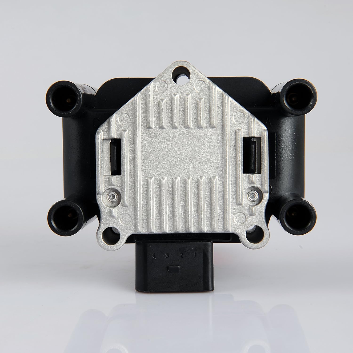
jag tänkte använda denna tändspole:Tips är Optokopplare, Metall låda, skärmad kabel, ingjutning med epoxy (mycket vibrationer), bra kvalitet på kontakt don, separat/filtrerad matningsspänning för din arduino. och en riktigt bra unpolär hallswitch. Daz Arduino Pro Mini är liten o fin att använda som enhet om du blir klar lätta att gjuta in.
VAG part 032905106B/032905106E
När du säger Optokoplare, menar du mellan Arduino och tändspolens ignitor (transistorkrets)? Matningsspänning. Hur tycker du jag ska mata arduinon? Jag tänkte använda Arduino Nano som jag gjuter in med epoxy i en metallåda. Tänkte inte ha några kontakter alls, endast löda kablarna rakt in på kortet och låta kablarna gå ut genom lådan med skärmning ända ut till sensorn och tändspolen. Skulle denna krets fungera bra om jag kopplade den till pin VIN? En bra hall sensor? Jag behöver ju en latchande hall sensor till mitt system. Den går hög vid nordlig magnetism och låg vid sydlig magnetism, på så vis vet jag vilka tändstift som är på tur.
Jag tänkte använda två sensorer paralellkopplade med varandra ingjutna i ett aluminiumrör. Skulle denna sensor fungera bra för det?
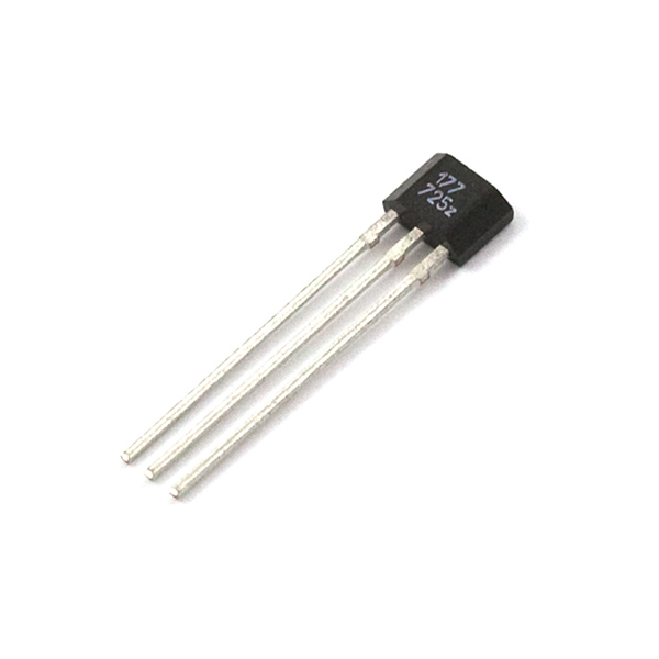
https://www.sparkfun.com/products/9312
Eller denna sensor:
http://www.electrokit.com/ats177-sip3-h ... atch.48516

Du har inte behörighet att öppna de filer som bifogats till detta inlägg.
Re: Elektroniskt tändsystem med Arduino
Yo! Brochan,
Gött ser bra ut, vad snabb du är med koden.
Optokopplaren. Transistor = Emitter Kollektor o Bas. Låt inte basen hänga i luften fast man kan. sök på google optocoupler and bas.
Jag vet inte hur du skall mata eländet. är det via batteri eller tändspolen?. det är rätt så mycket skyddsdioder. hoppa inte över TVS 'en den är bra sätt två i parallell på denna typ.
Hall = jättetrött kollar databladen i morron.
jag hade jätteproblem med EMC så innan jag fick i ordning på allt så, spenderades en del tid på meningslösheter.
- Skärmningen skall sitta ihop på ett ställe. i lådans chassis med så kort jordfläta som möjligt. Störningen från tändspolen är BRUTAL. jag har satt en ferrit på tändspolen. det hjälpte lite extra när jag kollade med mitt skåp osso skärmad kabel till alla signaler, hall switchar etc. Arduinon är cool men inte okänslig för spikar. OK. har du ett ocilloskåp eller kan du låna ett. det kan vara bra för att itta div felkällor , störningar.
Gött ser bra ut, vad snabb du är med koden.
Optokopplaren. Transistor = Emitter Kollektor o Bas. Låt inte basen hänga i luften fast man kan. sök på google optocoupler and bas.
Jag vet inte hur du skall mata eländet. är det via batteri eller tändspolen?. det är rätt så mycket skyddsdioder. hoppa inte över TVS 'en den är bra sätt två i parallell på denna typ.
Hall = jättetrött kollar databladen i morron.
jag hade jätteproblem med EMC så innan jag fick i ordning på allt så, spenderades en del tid på meningslösheter.
"endast löda kablarna rakt in på kortet och låta kablarna gå ut genom lådan med skärmning ända ut till sensorn och tändspolen."
- Skärmningen skall sitta ihop på ett ställe. i lådans chassis med så kort jordfläta som möjligt. Störningen från tändspolen är BRUTAL. jag har satt en ferrit på tändspolen. det hjälpte lite extra när jag kollade med mitt skåp osso skärmad kabel till alla signaler, hall switchar etc. Arduinon är cool men inte okänslig för spikar. OK. har du ett ocilloskåp eller kan du låna ett. det kan vara bra för att itta div felkällor , störningar.
-
Stenhammar
- Inlägg: 21
- Blev medlem: 9 april 2015, 20:18:25
Re: Elektroniskt tändsystem med Arduino
En uppdaterad kod och en ny signal simulator (2 signaler per varv).
En nördig film:
Tändsystem:
En Simulator:
En nördig film:
Tändsystem:
Kod: Markera allt
/****Simple reliable Electronic Ignition System for 4-stroke 4-cylinder wasted spark ignition system.
*****By Anders Stenhammar. 2016, Sweden **********/

// To be able to manipulate the AVR processor timers:
#include <Avr/interrupt.h>
#include <Avr/io.h>

//Pin definitions:
const byte HallPin1 = 2; // Pin nr 2  to Hall sensor
const byte HallPin2 = 3; // Pin nr 3 is also to Hall sensor
const byte IgnOnPin = 4; // Ignition switch
const byte Ign1Pin = 8;  // (PORTB,0)
const byte Ign2Pin = 12; // (PORTB,4)

volatile unsigned int cranktime;         // Time from 3 degrees to where the coil should start to load.
volatile unsigned int crankingDwellTime; // The time the coil should charge during cranking
volatile long int microseconds;          // The microsecondcounter value.
volatile long int half_revolution_time;  // The time it takes for the crank to turn 1/2 revolution.
volatile int runningDwellTime;           // The time the coil should charge during running
volatile int dwellTime;                  // The time the coil should charge.
volatile int IgnSystem;                  // Statusword for active ign system.
volatile byte IgnOn;


/***********************************************************************/
void setup() {

  pinMode(Ign1Pin, OUTPUT);    // Initialize   the Ignition 1 pin as an output.
  pinMode(Ign2Pin, OUTPUT);    // -"-
  pinMode(HallPin1, INPUT_PULLUP); // To get rid of RFI interference
  pinMode(HallPin2, INPUT_PULLUP); // -"-
  pinMode(IgnOnPin, INPUT_PULLUP); // -"-

  bitClear(PORTB, 0);          //digitalWrite(Ign2Pin, LOW);  //Turn the ignition off in case it's on
  bitClear(PORTB, 4);          //digitalWrite(Ign1Pin, LOW);  //   -"-

  attachInterrupt(digitalPinToInterrupt(HallPin1), SensorOn, RISING);   //Hall sensor DI for Ignition 1
  attachInterrupt(digitalPinToInterrupt(HallPin2), SensorOff, FALLING); //-"- 2

  crankingDwellTime = 4000;     //in uS
  runningDwellTime = 3000;      //in uS
  half_revolution_time = 0;
  IgnSystem = 0;               // No ignition system is active (cranking mode).
  IgnOn=LOW;
  IgnOn = digitalRead(IgnOnPin);

  /********** Setup timer2*************/
  noInterrupts();
  TCCR2A = 0;               // Turn off Control register for waveform generation
  TCCR2B = 0;               // Turn off noise cancelling, turn off edge select, waveform gen mode 0,
  TCCR2A |= (1 << WGM21);   // Turn on CTC mode (so it will start again) automatically
  TIMSK2 |= (1 << OCIE2A);  // Set interrupt on compare match.
  OCR2A = 8;                // Prescaler of 64 gives 4uS per tick, 4uS * 8 = 32uS (32uS = 1 degree at ~5100rpm).
  TCNT2  = 0;               // Reset timer counter to 0
  microseconds = 0;         // Preset the us counter variable.
  interrupts();
}
//========================================================================
/* The interrupt action for magnet 1: The Timer starts to count up 32 uS at a time.
**********************/
void SensorOff () {

 if (IgnOn == HIGH){
  half_revolution_time = microseconds;      // For engine speed measurement
  TCNT2 = 0;                                // Reset the timer count to 0
  microseconds = 0;                         // reset the uS counter variable
  TCCR2B |= (1 << CS22);                    // Load 64 prescaler, and this starts the timer2!

// While cranking (rpm < 300), the coil nr 2 will start to charge at once.
   if ((half_revolution_time>100000)||(half_revolution_time==0)) {
    IgnSystem = 2;
    bitSet(PORTB,4);                       //digitalWrite(Ign2Pin, HIGH); // (Turn on coil 2 charging immediately.)
    dwellTime = crankingDwellTime;          //Setting the dwelltime for cranking.
    cranktime = 0;                          //Setting the cranktime to 0 for immediate coil charging.
  }
// While running (rpm >= 300), coil nr 2 will be used at next ignition.
  if ((half_revolution_time<=100000)&&(half_revolution_time!=0)){
    IgnSystem = 1;                         //start using coil nr1 instead.
    dwellTime = runningDwellTime;          //setting the dwelltime for running
    }
   }
  }
/*========================================================================
 The interrupt action for magnet 2: The Timer starts to count up 32uS at a time.
********************************/
void SensorOn () {

  if (IgnOn == HIGH){
   half_revolution_time = microseconds;      // For engine speed measurement
  TCNT2 = 0;                                // Reset the timer count to 0
  microseconds = 0;                         // reset the uS counter variable
   TCCR2B |= (1 << CS22);                    // Load 64 prescaler, and this starts the timer2!

// While cranking (rpm < 300), the coil nr 1 will start to charge at once.
 if ((half_revolution_time>100000)||(half_revolution_time==0)) {
    IgnSystem = 1;
    bitSet(PORTB,0);                       //digitalWrite(Ign1Pin, HIGH); // (Turn on coil 1 charging immediately,)
    dwellTime = crankingDwellTime;          //setting the dwelltime for cranking.
    cranktime = 0;                          //Setting the cranktime to 0 for immediate coil charging.
    }
// While running (rpm >= 300), coil nr 2 will be used at next ignition.
    if ((half_revolution_time<=100000)&&(half_revolution_time!=0)){
     IgnSystem = 2;                         //start using coil nr2 instead.
     dwellTime = runningDwellTime;          //setting the dwelltime for running
     }
    }
   }
/*=============================================================================
 The Interrupt Service Routine for Timer2 that will be executed each time the timer reach the compare match register (32uS)*/
 ISR(TIMER2_COMPA_vect) {

  microseconds=microseconds+32;  // Increases the variable "microseconds" by 32 every time the ISR is executed).

 /************ coil charging*****************************/
  if ((microseconds >= cranktime) && (microseconds < (cranktime+dwellTime))) {

    if (IgnSystem == 1) {   //If ignitionsystem 1 is selected, then:
      bitSet(PORTB,0);     //(Turn on coil 1 charging.) //digitalWrite(Ign1Pin, HIGH);
    } if (IgnSystem == 2) { //If ignitionsystem 2 is selected, then:
        bitSet(PORTB,4);   //(Turn on coil 2 charging.)  //digitalWrite(Ign2Pin, HIGH);
    }
  }
 /***********Discharge coilspark*******************************************/
  // When the microseconds has reached the cranktime and dwelltime, then:
  if (microseconds >=(cranktime + dwellTime)) {
    bitClear(PORTB, 0); //digitalWrite(Ign1Pin, LOW);  //( Stop charging coil 1. (Gives spark))
    bitClear(PORTB, 4); // digitalWrite(Ign2Pin, LOW);  // As above.
            // _________________________________________________________________________________________________________
  if (microseconds > 100000) { // If the engine has stopped or still cranking, stop and reset the timer.
    TCCR2B &= ~(1 << CS22);    // Clear the prescaler, and this stops the timer2!
   TCCR2B = 0;
   microseconds = 0;
  }
 }
 }

/***********************************************************/
void loop() {

  IgnOn = digitalRead(IgnOnPin); // Check the status of the ignition switch

 // Ignition advance curve.
//Following numbers are based on a excell sheet with the advance curve attached.

if (half_revolution_time> 6208 ){ ///Advance 0 @ >4100 rpm (rev limitation)
 cranktime=7195-dwellTime;}

if ((half_revolution_time<=  7500 ) && (half_revolution_time> 7317 )){ ///Advance 28 @  4000-4100 rpm (rev limitation)
 cranktime=6208-dwellTime;}

 if ((half_revolution_time<=  9091 ) && (half_revolution_time> 7500 )){ ///Advance  28 @  4000-3300 rpm
 cranktime=7525-dwellTime;}

if ((half_revolution_time<=  10000 ) && (half_revolution_time> 9091 )){ ///Advance 27,5 @  3300-3000 rpm
 cranktime=8306-dwellTime;}

if ((half_revolution_time<=  10714 ) && (half_revolution_time> 10000 )){ ///Advance 27  @  3000-2800 rpm
 cranktime=8929-dwellTime;}

if ((half_revolution_time<= 11111 ) && (half_revolution_time>  10714 )){ ///Advance 26  @  2800-2700 rpm
 cranktime=9321-dwellTime;}

 if ((half_revolution_time<= 12500  ) && (half_revolution_time> 11111 )){ ///Advance 24 @  2700-2400 rpm
 cranktime=10625-dwellTime;}

if ((half_revolution_time<= 15000  ) && (half_revolution_time> 12500 )){ ///Advance 22 @  2400-2000 rpm
 cranktime=12917-dwellTime;}

if ((half_revolution_time<= 15789  ) && (half_revolution_time> 15000 )){ ///Advance 20 @  2000-1900 rpm
 cranktime=13772-dwellTime;}

if ((half_revolution_time<= 16667  ) && (half_revolution_time> 15789 )){ ///Advance 18  1900-1800 rpm
 cranktime=14722-dwellTime;}

if ((half_revolution_time<= 18750 ) && (half_revolution_time>= 16667 )){ //Advance 16 @ 1800-1600 rpm
cranktime=16771-dwellTime;}

if ((half_revolution_time<= 20000 ) && (half_revolution_time>= 18750 )){ //Advance 14 @ 1600-1500 rpm
cranktime=18111-dwellTime;}

if ((half_revolution_time<= 21429 ) && (half_revolution_time>=20000  )){ //Advance 12 @ 1500-1400 rpm
cranktime=19643-dwellTime;}

if ((half_revolution_time<=25000  ) && (half_revolution_time>= 21429 )){ //Advance 10 @ 1400-1200 rpm
cranktime=23194-dwellTime;}

if ((half_revolution_time<=27273  ) && (half_revolution_time>=25000  )){ //Advance 9 @ 1200-1100 rpm
cranktime=25455-dwellTime;}

if ((half_revolution_time<= 30000) && (half_revolution_time>=27273  )){ //Advance 8 @ 1100-1000 rpm
cranktime=28167-dwellTime;}

if ((half_revolution_time<=  33333) && (half_revolution_time>= 30000 )){ //Advance 7,5 @ 1000-900 rpm
cranktime=31389-dwellTime;}

if ((half_revolution_time<=42857  ) && (half_revolution_time>= 33333 )){ //Advance 7 @ 900-700 rpm
cranktime=40476-dwellTime;}

if ((half_revolution_time<=50000  ) && (half_revolution_time>= 42857)){ //Advance 7 @ 700-600 rpm
cranktime=47222-dwellTime;}

if ((half_revolution_time<= 75000 ) && (half_revolution_time>= 50000 )){ //Advance 9 @ 600-400 rpm
cranktime=70000-dwellTime;}

if ((half_revolution_time<=  85714) && (half_revolution_time>= 75000 )){ //Advance 2 @ 400-350 rpm
cranktime=83333-dwellTime;}

if ((half_revolution_time<= 100000 ) && (half_revolution_time>= 85714 )){ //Advance -2,5 @ 350-300 rpm
cranktime=99722-dwellTime;}

}
// Thank you for helping me improve this code. Please send feedback to anders.stenhammar84@gmail.com
Kod: Markera allt
//Use Serial monitor to send rpm setting to the simulator.
//Default RPM is 250

// To be able to manipulate the AVR processor timers:
#include <Avr/interrupt.h>
#include <Avr/io.h>
const int HallPin1 = 13;  // Hall latch sensor output (PORTB,0)
const int HallPin2 = 12;  // Hall latch sensor output (PORTB,0)
int TrimPotPin = A0;    // select the input pin for the potentiometer
unsigned int rpm;
long int timeold;
unsigned int sensorValue;
volatile long int microseconds;          // The microsecondcounter value.
volatile long int half_revolution_time;  // The time it takes for the crank to turn 1/2 revolution (The value of Trimpot.
volatile long half_revolutionStart;
volatile int half_revolutions;      // Hall sensor trigger counter

void setup() {

 Serial.begin(9600);
 pinMode(HallPin1, OUTPUT);
 digitalWrite(HallPin1, LOW);

rpm=250;
  microseconds = 0;         // Preset the us counter variable.

   /********** Setup timer2*************/
  noInterrupts();
  TCCR2A = 0;               // Turn off Control register for waveform generation
  TCCR2B = 0;               // Turn off noise cancelling, turn off edge select, waveform gen mode 0,
  TCCR2A |= (1 << WGM21);   // Turn on CTC mode (so it will start again) automatically
  TIMSK2 |= (1 << OCIE2A);  // Set interrupt on compare match.
  OCR2A = 8;                // Prescaler of 64 gives 4uS per tick, 4uS * 8 = 32uS (32uS = 1 degree at ~5100rpm).
  TCNT2  = 0;               // Reset timer counter to 0
  TCCR2B |= (1 << CS22);    // Load 64 prescaler, and this starts the timer2!
  interrupts();

}
 //The Interrupt Service Routine for Timer2 that will be executed each time the timer reach the compare match register (32uS)*/
 //______________________________________________________________________________________________________________________________
 ISR(TIMER2_COMPA_vect) {

  microseconds=microseconds+32;  // Increases the variable "microseconds" by 32 every time the ISR is executed).

  if (microseconds <= half_revolution_time){
     digitalWrite(HallPin1, HIGH); // North magnet is passing the Hall sensor
     }
     if (microseconds > half_revolution_time){
     digitalWrite(HallPin1, LOW); // South magnet is passing the Hall sensor
     }
     if (microseconds > (half_revolution_time*2)){
     half_revolutions=half_revolutions+2;
     microseconds = 0;         // Reset the us counter variable.
     TCNT2  = 0;               // Reset timer counter to 0
     }
 }

void loop() {
  half_revolution_time=30000000/rpm;

 if (Serial.available() > 0) { // send data only when you receive data:

  rpm = Serial.parseInt(); //read int or parseFloat for ..float...

  // say what you got:
  Serial.print("rpm: ");
  Serial.println(rpm, DEC);
  }
}
-
Stenhammar
- Inlägg: 21
- Blev medlem: 9 april 2015, 20:18:25
Re: Elektroniskt tändsystem med Arduino
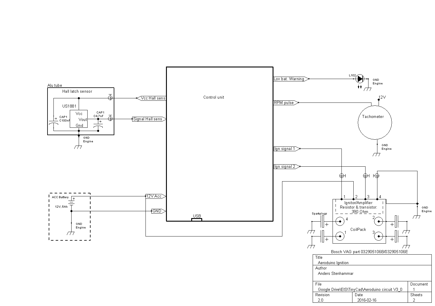
Nu har jag knåpat ihop ett elschema. Vad tycker ni om det? Några galna kopplingar eller komponentval? Spänningsgulatorerna, späningsreferenskopplingen, mellanstegskopplingen mellan arduino-ignitor och RPM signalen har jag snott från http://speeduino.com och http://www.sportdevices.com/ignition/ignition.htm#TCI Resten är "ihopaplock". Det sitter två batterier för säkerhetskull. Jag planerar att sen ha en arduino per batteri som jobbar parallellt mot en tändspole/packe.
Du har inte behörighet att öppna de filer som bifogats till detta inlägg.
Re: Elektroniskt tändsystem med Arduino
Kul projekt!
Gjorde ett mini-insprutningssystem med Arduino, bränsle delen med CDI som trigger input.
Hade lite störningsproblem i början, men det löste sig med plåt och jordning
Gjorde ett mini-insprutningssystem med Arduino, bränsle delen med CDI som trigger input.
Hade lite störningsproblem i början, men det löste sig med plåt och jordning
-
Stenhammar
- Inlägg: 21
- Blev medlem: 9 april 2015, 20:18:25
Re: Elektroniskt tändsystem med Arduino
Spännande! Har du någon dokumentation att dela med dig? Hur gjorde du med jordningen, jordade du både arduinon och tändsystemet i motorblocket?Gjorde ett mini-insprutningssystem med Arduino, bränsle delen med CDI som trigger input.
Vill du kolla min elritning och se om du hittar några fel eller tokigheter?
Re: Elektroniskt tändsystem med Arduino
Ska se om jag hittar något, detta var ett tag sen och var mer ett "snabbhack". Men om jag inte minns fel så försökte jag jorda så mycket som möjligt direkt till batteriet.
-
Stenhammar
- Inlägg: 21
- Blev medlem: 9 april 2015, 20:18:25
Re: Elektroniskt tändsystem med Arduino
Någon som har någon input på denna koppling? Är det vettigt kopplat? Det kommer matas av ett 12V bilbatteri och generator. Ritningen är gjortd i TinyCad men filer går inte att bifoga.Jag kan skicka den via epost om någon vill ha den.
Någon som kan ge mig tips på hur jag ska ordna kylningen till regulatorn. Allt ska ju ligga inbakat i en plåtlåda som kabelskärmarna ska anslutas till... Skall plåtlådan jordas till motorblocket och bilbatteriet?

Någon som kan ge mig tips på hur jag ska ordna kylningen till regulatorn. Allt ska ju ligga inbakat i en plåtlåda som kabelskärmarna ska anslutas till... Skall plåtlådan jordas till motorblocket och bilbatteriet?
Du har inte behörighet att öppna de filer som bifogats till detta inlägg.
-
Stenhammar
- Inlägg: 21
- Blev medlem: 9 april 2015, 20:18:25
Re: Elektroniskt tändsystem med Arduino
Hej.
Du nämnde ingjutning av tändsystemet. Vad använda du för material? Epoxy krymper och bli ju varmt så det kan ju slita loss ytmonterade komponenter. Det finns ju dyra specialmedel att köpa, men de säljer oftast inte till privatpersoner. Vad har du för erfarenhet av detta?
MVH Anders
Du nämnde ingjutning av tändsystemet. Vad använda du för material? Epoxy krymper och bli ju varmt så det kan ju slita loss ytmonterade komponenter. Det finns ju dyra specialmedel att köpa, men de säljer oftast inte till privatpersoner. Vad har du för erfarenhet av detta?
MVH Anders
M_Sander skrev:Yo! Brochan,
Gött ser bra ut, vad snabb du är med koden.
Optokopplaren. Transistor = Emitter Kollektor o Bas. Låt inte basen hänga i luften fast man kan. sök på google optocoupler and bas.
Jag vet inte hur du skall mata eländet. är det via batteri eller tändspolen?. det är rätt så mycket skyddsdioder. hoppa inte över TVS 'en den är bra sätt två i parallell på denna typ.
Hall = jättetrött kollar databladen i morron.
jag hade jätteproblem med EMC så innan jag fick i ordning på allt så, spenderades en del tid på meningslösheter.
"endast löda kablarna rakt in på kortet och låta kablarna gå ut genom lådan med skärmning ända ut till sensorn och tändspolen."
- Skärmningen skall sitta ihop på ett ställe. i lådans chassis med så kort jordfläta som möjligt. Störningen från tändspolen är BRUTAL. jag har satt en ferrit på tändspolen. det hjälpte lite extra när jag kollade med mitt skåp osso skärmad kabel till alla signaler, hall switchar etc. Arduinon är cool men inte okänslig för spikar. OK. har du ett ocilloskåp eller kan du låna ett. det kan vara bra för att itta div felkällor , störningar.
-
Stenhammar
- Inlägg: 21
- Blev medlem: 9 april 2015, 20:18:25
Re: Elektroniskt tändsystem med Arduino
Aeroduino EIS version 3.0
Efter en hel del hjälp så har ritningen ändrats markant. Mer skydd och tydlighet. Vad tycker ni?
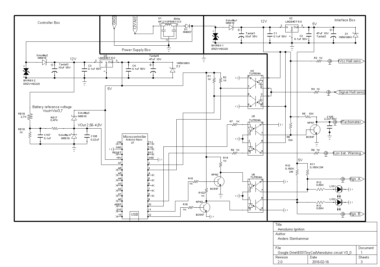
Efter en hel del hjälp så har ritningen ändrats markant. Mer skydd och tydlighet. Vad tycker ni?
Re: Elektroniskt tändsystem med Arduino
Kul projekt!
Har ni någon uppfattning om hur bra ett varvtalstyrt tändsystem kan bli jämfört med ett varv- och laststyrt tändsystem.
Med last menar jag att man tar in någon form av lastsignal från motorn, tillexempel luftmassa, trottelvinkel eller insugstryck.
Har ni någon uppfattning om hur bra ett varvtalstyrt tändsystem kan bli jämfört med ett varv- och laststyrt tändsystem.
Med last menar jag att man tar in någon form av lastsignal från motorn, tillexempel luftmassa, trottelvinkel eller insugstryck.

